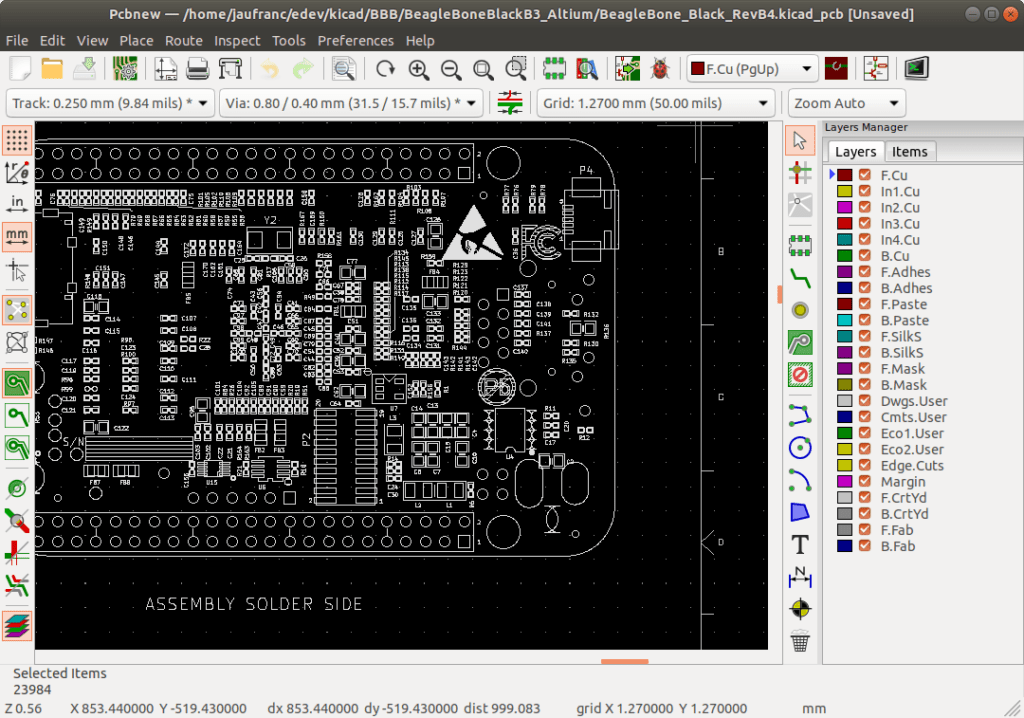
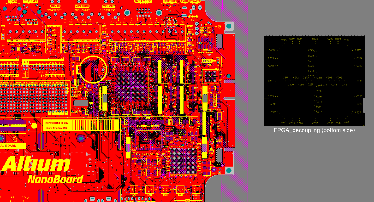
- Launch a.pcb file, or any other file on your PC, by double-clicking it. If your file associations are set up correctly, the application that's meant to open your.pcb file will open it. It's possible you may need to download or purchase the correct application.
- If you want to associate a file with a new program (e.g. My-file.PCB) you have two ways to do it. The first and the easiest one is to right-click on the selected PCB file. From the drop-down menu select 'Choose default program', then click 'Browse' and find the desired program. The whole operation must be confirmed by clicking OK.
The instructions that follow explain how to import files you download from Ultra Librarian into Altium Designer.
The file extension for NC Drill data created in the Altium Designer PCB Editor is.txt. Click to open the Browse For Folder dialog and navigate to the CAM Imports & Exports folder you extracted from the download ZIP mentioned at the start of this article, and click OK. Re: Pads.pcb file into Altium « Reply #12 on: April 18, 2019, 09:20:01 am » You know, when I had a problem importing OrCAD, I called Altium support and they sent me a step by step guide for it.
Before you begin your import, extract the files included in your zip download folder and save the files in a directory you can easily access from Altium Designer. The downloaded files are:
•UL_Form.dfm
•UL_Form.pas
•UL_Import.pas
•UL_Import.prjScr
To import a footprint, symbol, and 3D Model into Altium Designer:
1.Open Altium Designer.
2.Choose the File > Open menu items and select the downloaded UL_Import.PrjScr. This script is located in the AltiumDesigner folder you downloaded.
3.Click the Open button to automatically run the script.
Bully scholarship edition download mac. 4.Select UL_Form.pas > Open.
5.Select Run.
6.Select UL_Form.pas again.
7.Choose the AltiumDesigner.txt file included in your Ultra Librarian download.
8.Click the Start Import button.
After the import is complete, you can view and save the generated footprint and symbol.
To include the PCB 3D Model:
1.Open the PCB footprint.
2.Select the Place>3D Body menu items.
3.Select the Generic 3D Model radio option.
4.Under the 3D Model section, select the Embedded radio button and click the Load from file button.
5.Select the step file downloaded from Ultra Librarian.

6. Add a snap point and axes.
7.Click OK and place the body. The 3D Model is available from the 3D view.
To view your imported components:
1.Select the menu items: View > Workspace Panels > Systems > Projects.
2.Double-click the PCBLIB item you want to open from the Source Documents list.

Altium Pcb Viewer
3.Click the PCB button located in the lower right corner of the screen and select PCB Library from the pop-up menu.
You can browse through the components to view.
To view imported schematic symbols:
1.Click the tab labeled Projects and double-click the SchLib item you want to open.
News24.com Mozambique troops fight off attack near R292 billion LNG project; News24.com Elon Musk says it’s ‘impossible’ to take Tesla private, mulls new IPO. Harnet, Africa Business Consultant 'As founder of Africajumpstart.com and the new Africa Business in a Box importing program, I am determined to awaken the African Diaspora to the huge opportunities in Africa. Business in a box zagreb. Business in a Box will for fill all your needs. The “need to know guides” and “stunning easy to use templates”, will make the start up process seamless and make you feel like you are in the know how. Business‑in‑a‑Box helps you accomplish your most complicated tasks and projects with ease, speed and quality. Take Your Business To the Next Level. Business‑in‑a‑Box helps you make major progress.
2.Click the SCH button located in the lower right corner of the window.
3.Choose the SCH Library menu item from the pop-up menu to display items in the schematic library side panel.
Altium File Format

4.Browse through the components and view the schematic symbols in the display window.
PCB Development Path
Altium Pcb Design

Altium File Types
Each new project includes a new solution, new details, and new compromises to which the engineer MUST pay attention. In order to get the results closer to the ideal, the designer of the future device must make proper calculations, imagine the consequences of decisions made, compare different device configurations and, finally, make the right choice. Altium Designer offers a complete set of tools allowing the engineer to follow the PCB development path without leaving the design environment and without resorting to third-party programs. From the beginning of the project to its completion, the designer must perform many operations related to each particular stage of the development path. From these stages, as from the blocks, a typical design path is built.
The development path of every PCB always starts with creating a new project in which the design of the schematic and board will be carried out and synchronized. At this point, it is assumed that a library is created and placed in your repository. In this guide, you will use the existing library of managed components. After the project is created, work starts on the electrical schematic design on which the components are placed and their interconnections are defined. The Electrical Rules Check (ERC) design rules will be checked several times while working on the schematic, and once completed, the project will be compiled. The next step contains all the work related to PCB design. This step includes forming the board shape, creating a layer set (stackup), synchronizing with the schematic, design rules definition, components placement, routing, and much more. During PCB design, all rules such as Design For Assembly (DFA), Design Rules Check (DRC), and Design For Manufacture (DFM) are checked online, all of which help decrease errors and problems. After the PCB is completely designed and error-free, the documentation development stage begins including exporting the Bill Of Materials (BOM) exporting, creating assembly drawings, etc. The final step of the PCB development path is uploading files for the manufacturer to create a printed circuit board that will be used to create a finished device. These are the steps necessary in a typical PCB development path.


